
I wanted to have a single box that had both NES and SNES ports with a single USB cable to connect them all to the PC. The benefit of having a USB hub inside would allow me to put a flash drive inside with emulators and roms on it.
Equipment:
-
Broken NES
-
Broken SNES
-
USB Hub
-
26 gauge wire
-
RetroZone NES/SNES USB Kit (4) http://www.retrousb.com/product_info.php?cPath=21&products_id=44
Other tools:
-
Screw driver
-
Soldering Iron
-
Glue gun
-
Dremel (variable speed - works best for plastic)
-
ePoxy glue
The hardest part of converting the NES/SNES controller inputs to USB Joystick inputs was solved by the RetroZone’s NES/SNES USB kit. The kit comes with a USB cable and PCB with the necessary parts already soldered on. They have easy to use wiring diagrams on the website.
The Retro kit came with the PCB and USB cable soldered together. To save time and give me more options if I decide to take this apart at a later time I left them attached. This did mean I had to coil up a bunch of extra wires but the spacious room inside the NES made this pretty easy.
I tested each component as I finished them, which helped in finding wiring problems easier. Which is something I did run into with the SNES ports. To test if the port was working correctly I plugged it into the PC, then plugged the appropriate controller into the port. Then I open the “Game Controllers” app (built into Windows), go to the properties of the game pad (RetroZone Kits show up as “Retr”) and there you can see the X/Y Axis and the different buttons. Here is the button number to controller button mapping:
NES
-
B
-
A
-
Select
-
Start
SNES
-
Y
-
B
-
Select
-
Start
-
X
-
A
-
L
-
R
The SNES ports fit almost perfectly in the cartridge slot of the NES. I used a dremel to carve out some of the plastic from the NES lid. The plastic around the cartridge slot gives the SNES ports pretty good support for inserting and removing the SNES controllers. Later (after wiring them up) I used glue to hold them in place.

I chose to wire up the NES ports first. It was pretty easy because all of the wires were color coded. I cut the connector off the end and removed the blue and purple wires. The pins pull right out of the NES connector with a pair of needle nose pliers. I tinned the wires (add a little solder before actually soldering and letting it cool) and added solder to the pads on the Retro PCB. This makes soldering the wire to the Retro PCB board significantly easier.
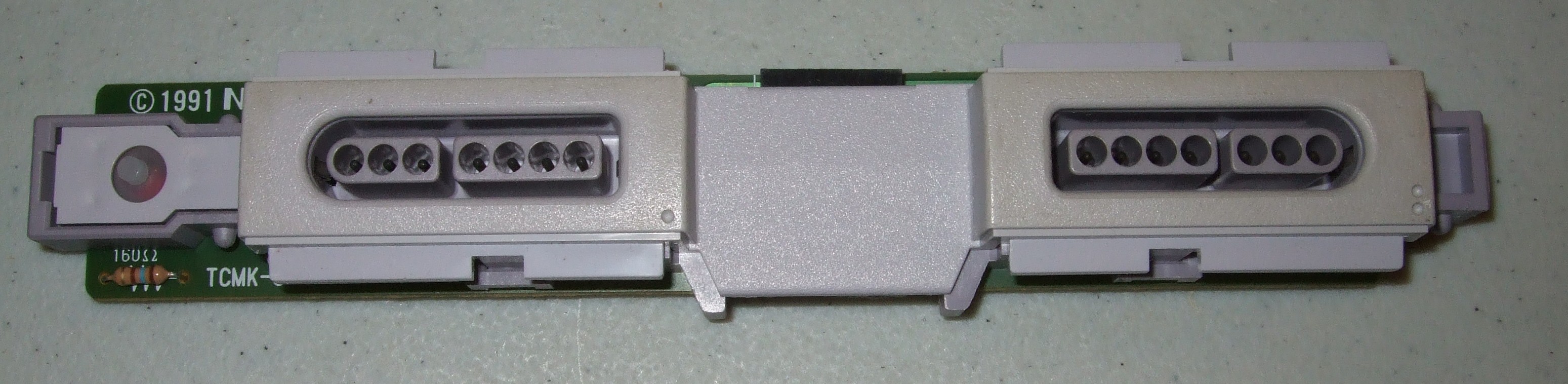

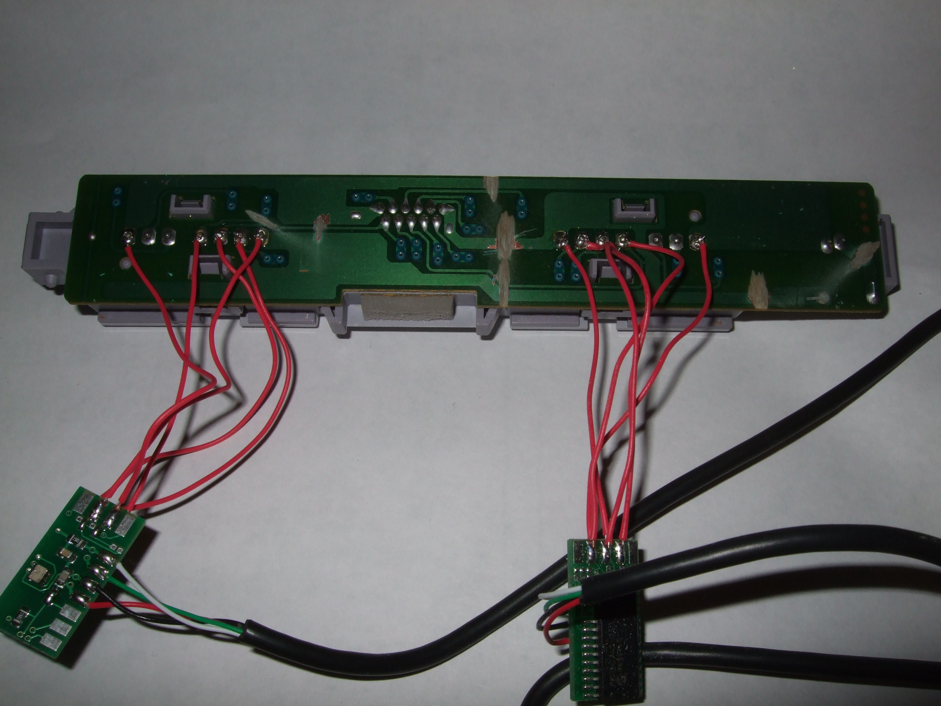
The SNES ports were soldered to a PCB board. The pinouts weren’t labeled or color coded so I used this (http://www.gamefaqs.com/snes/916396-snes/faqs/5395) wiring guide to match the pinout with the wire color that the Retro kit diagram had. I used 26 gauge wire to connect the SNES ports to the Retro Kit. Again tinning the wirings and the Retro Kit’s solder pads before actually soldering them together helped. I wired up the first port (player 1) and plugged it into my PC. It worked perfectly, something I wasn’t expecting was the power led (which is on the same PCB as the SNES controller ports) lit up. Then I wired up the second port (player 2).
While testing the SNES ports this time, nothing worked correctly. The player 1 port didn’t work at all and the player 2 port was having all kinds of cross talk between the buttons (the A button was being registered as button 1 & 2 being pressed). This can happen if you miss wire one of the ports. I double checked all the wiring and everything was good. Then I started looking at the traces on the PCB board. That’s when I noticed that some of the wires on the ports were connected via the traces on the PCB. Luckily all the traces were on the side of the board that was exposed. So I took my dremel and used it to scrape the traces off. That did the trick and now both of the ports are working.
 ))
))
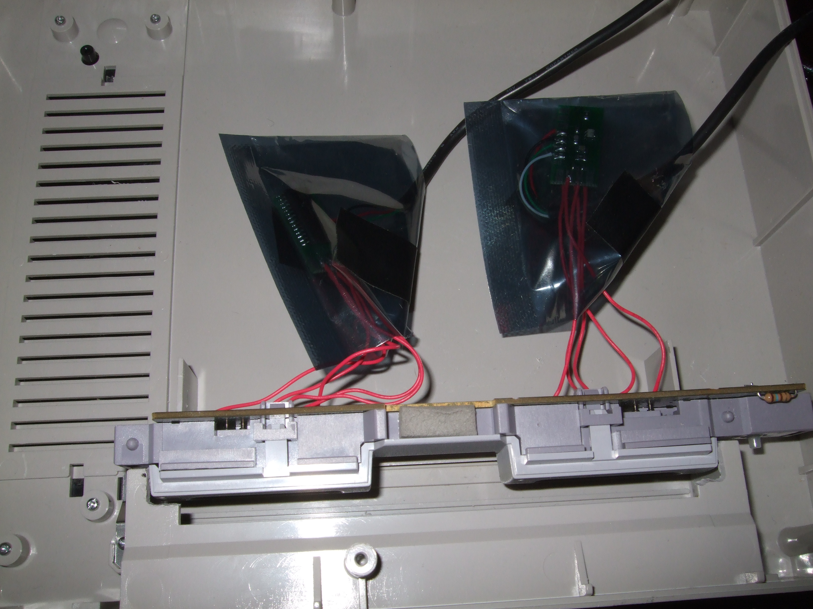
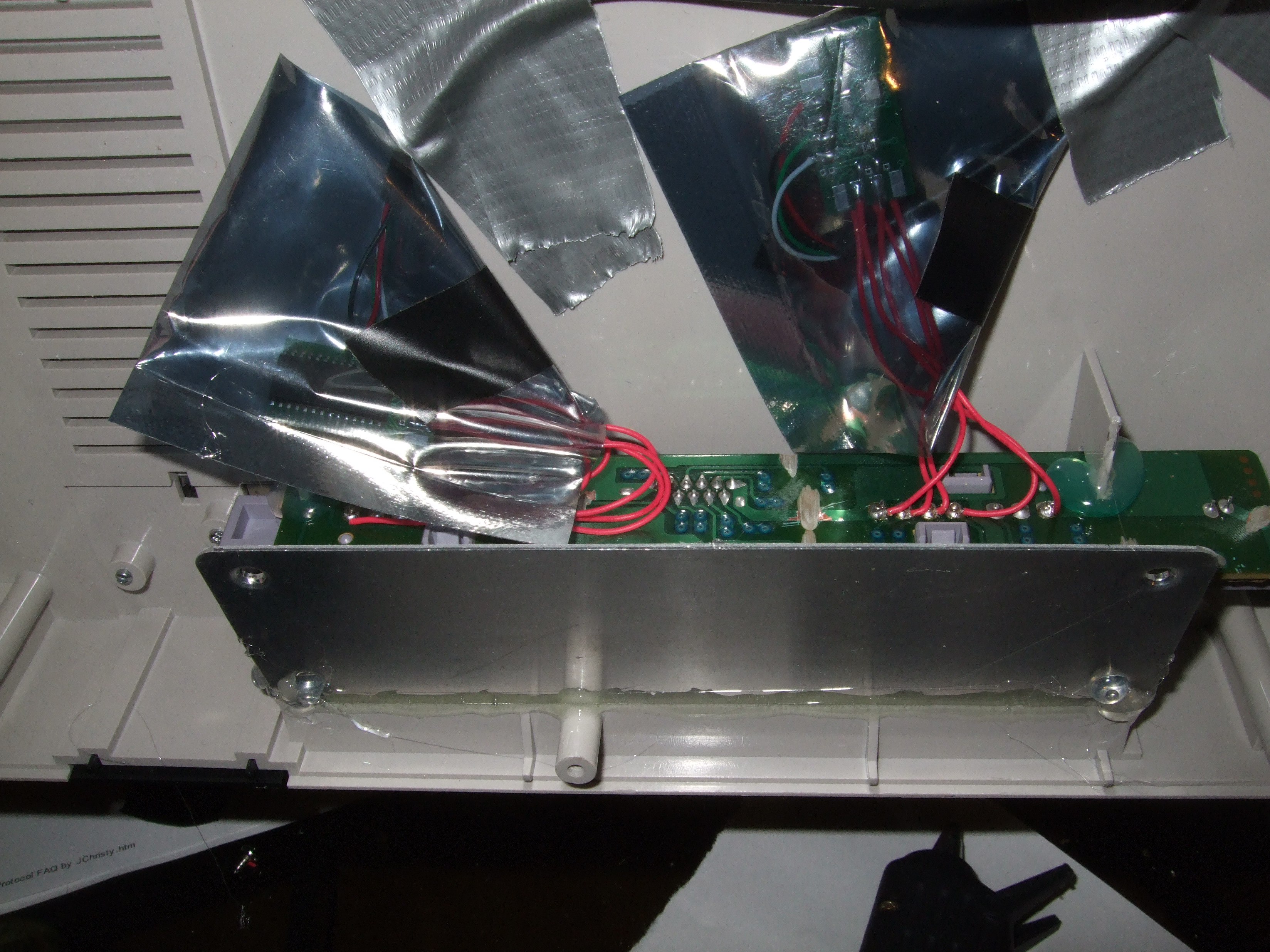
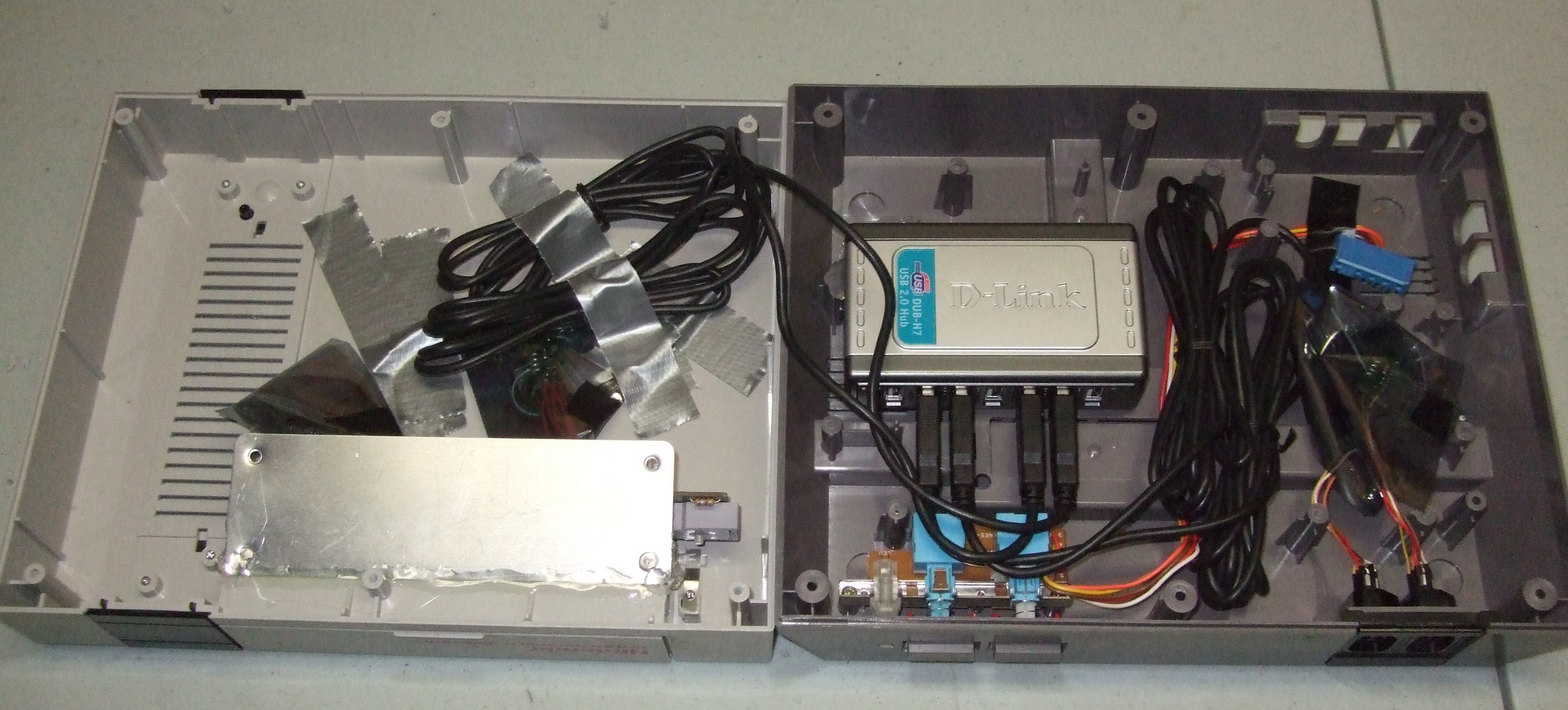
Now its time to put it all together. First I glued the SNES ports into the lid. I used epoxy and hot glue to get them to stay. I put the metal piece underneath the SNES ports and was going to screw it into place for added support but decided against it. I didn’t have the appropriate screws and didn’t want to risk them poking up through the lid. I put the RetroZone Kit in an anti-static bag to keep it from shorting. I taped the extra wire to the lid and left enough slack so I could remove the lid and set it next to the base without unplugging the USB cables from the USB hub.
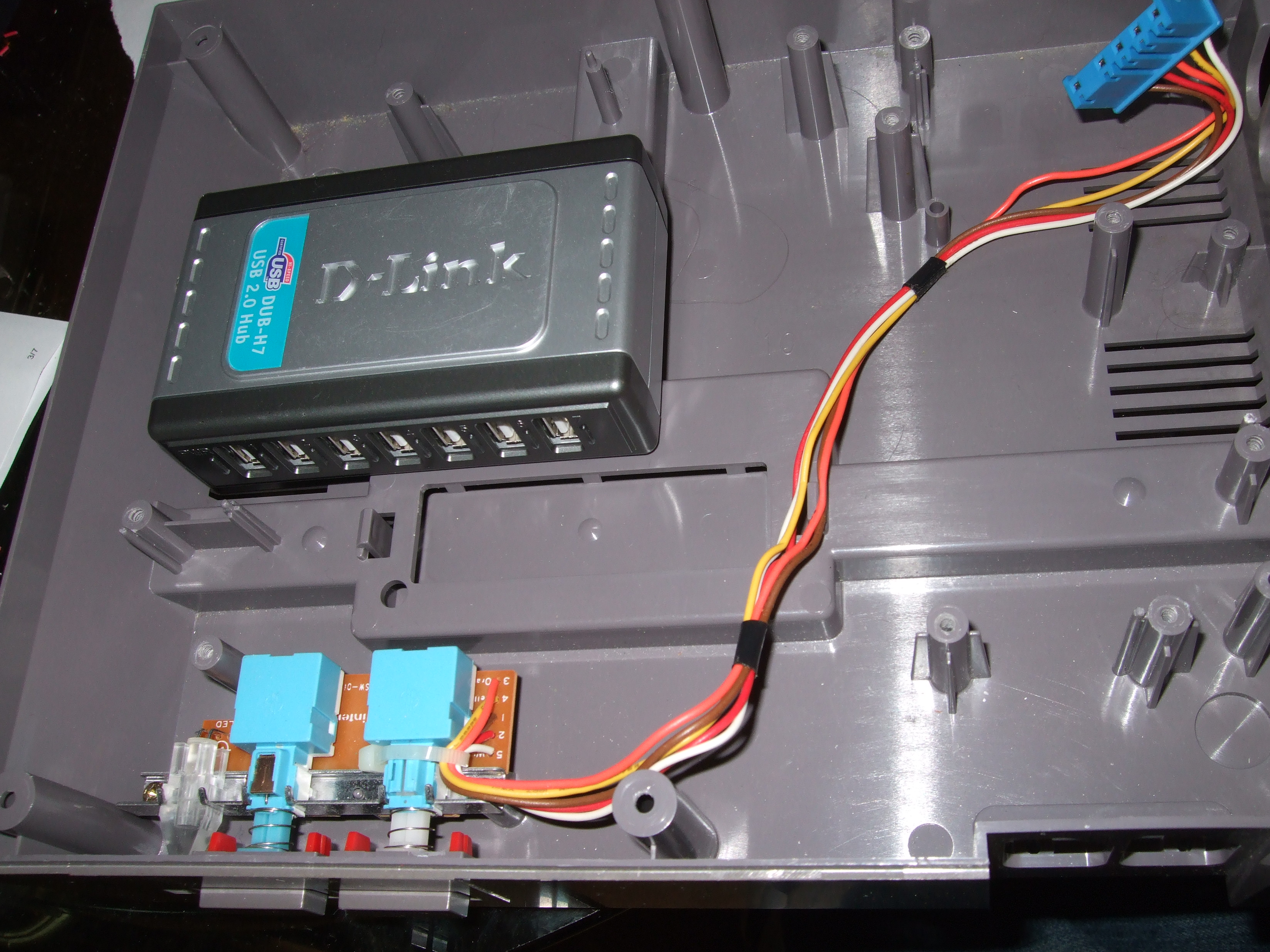
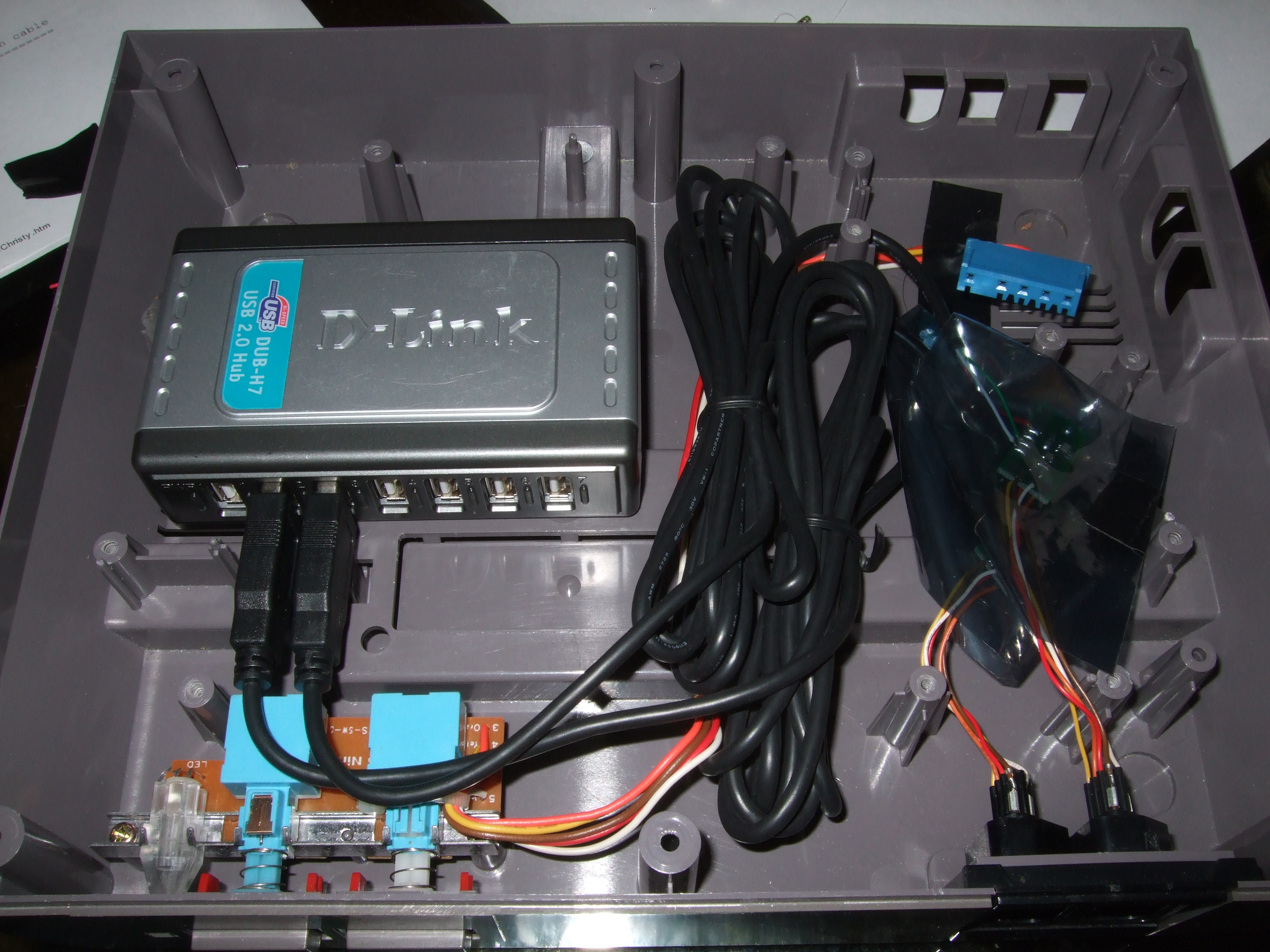
Next I used epoxy to hold the USB hub in place in the base of the NES. I made sure to position it so the ports would be accessible and connection in the back. It is a powered USB hub but I didn’t need the power cable because the gamepads and flash drive don’t draw that much power. I did leave the power port exposed in case I needed to add it later. I wrapped the USB cable coming out of the Hub around a plastic post to keep it from being ripped out or from yanking on the hub. I also zipped tied it to the back of the NES where it was coming out of.
The NES ports were easiest to install, then just went back into the spot they came out of. I wrapped up and taped the extra wire to the base.
Then I screwed the case back together, just using 4 screws instead of 6.
The final step was to make sure I didn’t mess anything up when putting it back together. All four ports worked, now its time to play some games.